
Extrude Kullanımı
İçindekiler
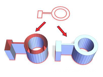
- Extrude Kullanımı 2 boyutlu bir nesneyi 3 boyutlu bir nesneye çevirmek isterseniz. Extrude yöntemini denemelisiniz. Spline hakkında şuradan ön bilgi edinebilirsiniz. Öncelikle Line komu ile aşağıdaki gibi bir odanın üstten görünüşünü 2 boyutlu olarak çiziyoruz. Odayı çizerken, bir çizime nasıl ekleme yapılır ondanda bash edelim. Aslında 2 farklı çizim yapmış olduk şimdi bu iki farklı çizimi birbirine bağlayalım. Parçalar üzerinde Convert To: Covert to Editable Spline seçeneğini seçiyoruz. Attach işlemi yaparak artık iki farklı 2 boyutlu çizimi tek boyuta indirmiş olacağız. Görüldüğü gibi move yapıldığında tek bir parça gibiler. Ancak hala işlem bitmedi. Nesnenin tamamını seçerek Weld işlemi uygulamak bu iki nesnenin kaynaşmasını sağlar. Zaten Weld kaynaklama demektir. Aynı Modifier List içerisindeki Spline bölümünde aşağıda Outline düğmesine basıyoruz ve girdiğimiz Outline değeri nesnemize kabuk yada et kalınlığı veriyor. Böylece duvarları oluşturmuş oluyoruz. Aynı nesneyi kopyalayıp çoğaltıyoruz. Nesnelerin hepsini seçip Modifier Listten Extrude seçeneğine tıklıyoruz. Girdiğimiz Amount değerine göre bir yükseklik tanımlanacak ve odalarımız oluşmuş olacaktır. Bir başka örnek Extrude Menüsü Amount—Sets the depth of the extrusion. Segments—Specifies the number of segments that will be created in the extruded object. Capping group Cap Start—Ekstrüde edilmiş nesnenin başlangıçı üzerindeki yüzeyi kapatır. Yani yukardaki duvarı Extrude ederken duvarın tabanını kapalı yapar. Cap End—Ekstrüde edilmiş nesnenin bitişi üzerindeki yüzeyi kapatır. Yani yukardaki duvarı Extrude ederken duvarın en üstünü kapalı yapar. Morph—Arranges cap faces in a predictable, repeatable pattern, which is necessary for creating Morph targets. Morph capping can generate long, thin faces that don't render or deform as well as grid capping. Use morph capping primarily if you're extruding multiple morph targets. Grid—Arranges cap faces in a square grid trimmed at the shape boundaries. This method produces a surface of evenly sized faces that can be deformed easily by other modifiers. When you choose the Grid capping option, the grid lines are hidden edges rather than visible edges. This primarily affects any objects assigned a material with the Wire option turned on, or any objects that use the Lattice modifier. Output group Patch—Produces an object that you can collapse to a patch object; see the Edit Modifier Stack section in Modifier Stack. Mesh—Produces an object that you can collapse to a mesh object; see the Edit Modifier Stack section in Modifier Stack. NURBS—Produces an object that you can collapse to a NURBS surface; see the Edit Modifier Stack section in Modifier Stack. Generate Mapping Coords—Creates the extruded object with mapping coordinates already applied. When Generate Mapping Coordinates is turned on, additional mapping coordinates are applied to the end caps placing a single 1 x 1 tile on each cap. Generate Material IDs—Assigns different material IDs to the sides and the caps of the extruded object. Specifically, the sides receive ID 3, and the caps receive IDs 1 and 2. This check box is turned on as a default when you create an extruded object, but if you load an extruded object from a .max file, the check box is turned off, maintaining the same material ID assignment for that object as it had in R1.x. Use Shape IDs—Uses the material ID values assigned to segments in the spline you extruded, or curve sub-objects in the NURBS curve you extruded. Smooth—Extrude yapılan nesneye yumuşatma uygular.
- 2 boyutlu bir nesneyi 3 boyutlu bir nesneye çevirmek isterseniz. Extrude yöntemini denemelisiniz.
- Extrude Menüsü
Extrude Kullanımı
2 boyutlu bir nesneyi 3 boyutlu bir nesneye çevirmek isterseniz. Extrude yöntemini denemelisiniz.
Spline hakkında şuradan ön bilgi edinebilirsiniz.
Öncelikle Line komu ile aşağıdaki gibi bir odanın üstten görünüşünü 2 boyutlu olarak çiziyoruz.
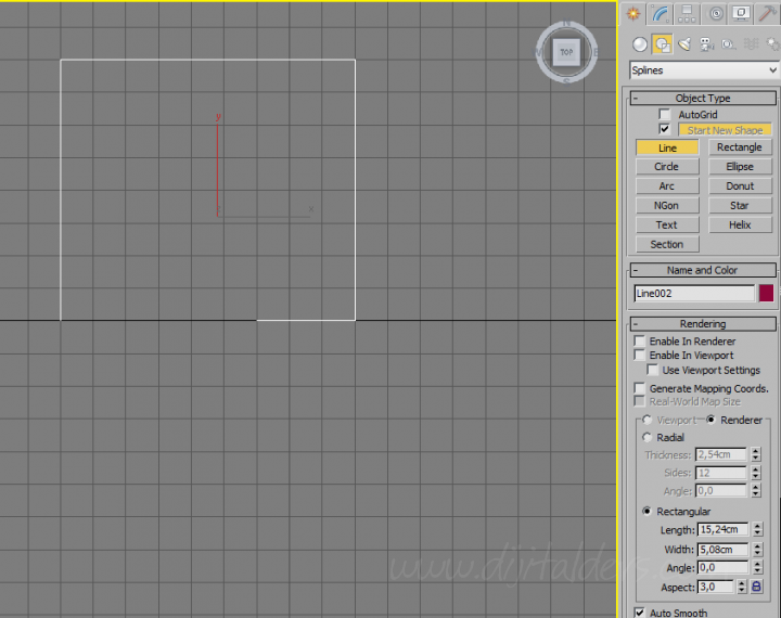
Odayı çizerken, bir çizime nasıl ekleme yapılır ondanda bash edelim.
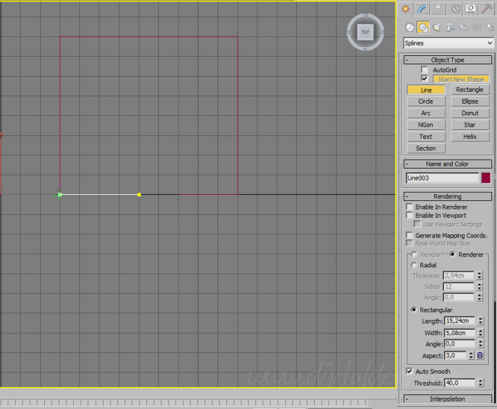
Aslında 2 farklı çizim yapmış olduk şimdi bu iki farklı çizimi birbirine bağlayalım.
Parçalar üzerinde Convert To: Covert to Editable Spline seçeneğini seçiyoruz.
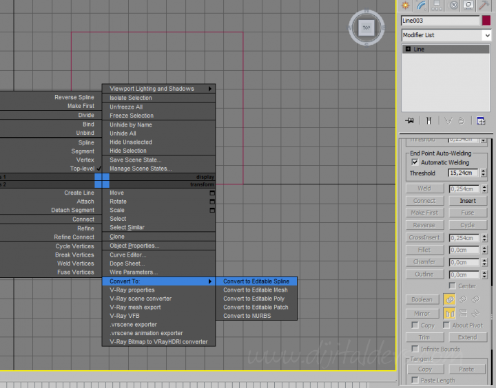
Attach işlemi yaparak artık iki farklı 2 boyutlu çizimi tek boyuta indirmiş olacağız.
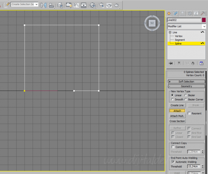
Görüldüğü gibi move yapıldığında tek bir parça gibiler.
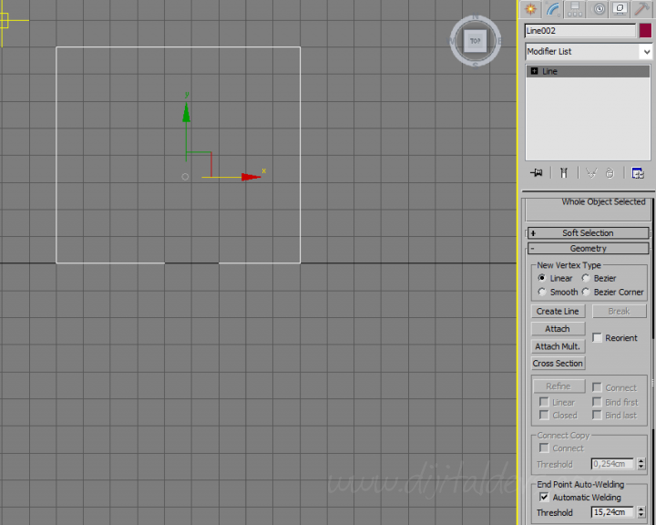
Ancak hala işlem bitmedi. Nesnenin tamamını seçerek Weld işlemi uygulamak bu iki nesnenin kaynaşmasını sağlar. Zaten Weld kaynaklama demektir.
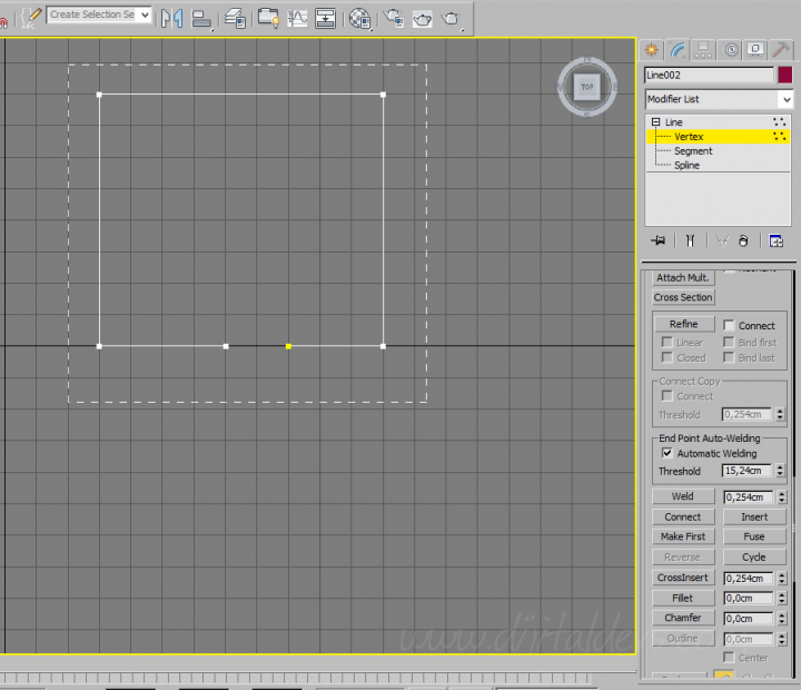
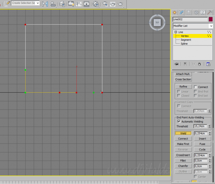
Aynı Modifier List içerisindeki Spline bölümünde aşağıda Outline düğmesine basıyoruz ve girdiğimiz Outline değeri nesnemize kabuk yada et kalınlığı veriyor. Böylece duvarları oluşturmuş oluyoruz.
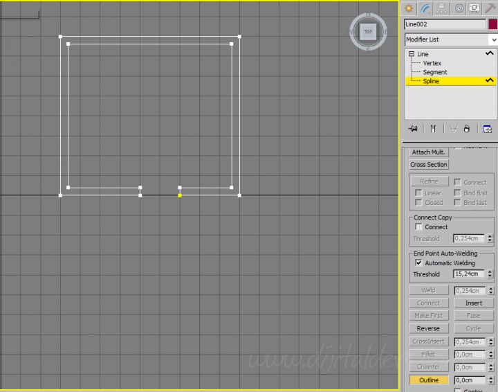
Aynı nesneyi kopyalayıp çoğaltıyoruz.
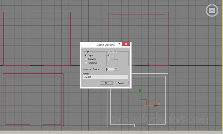
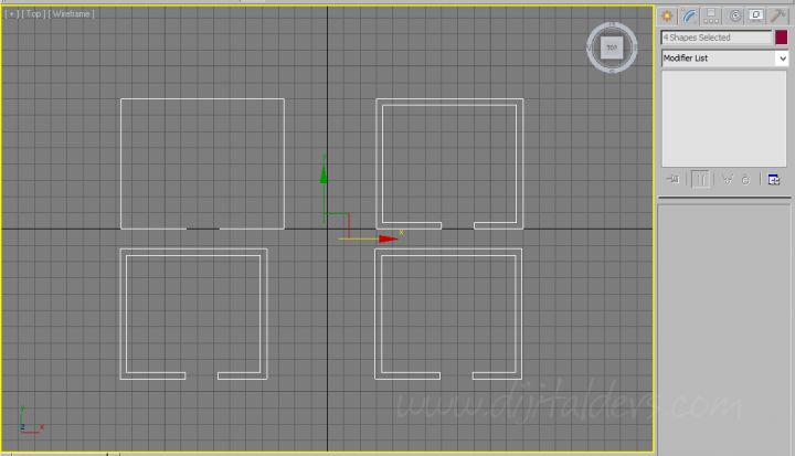
Nesnelerin hepsini seçip Modifier Listten Extrude seçeneğine tıklıyoruz.
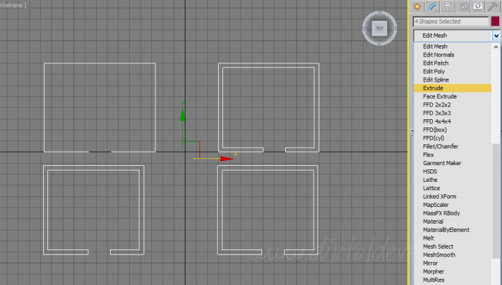
Girdiğimiz Amount değerine göre bir yükseklik tanımlanacak ve odalarımız oluşmuş olacaktır.
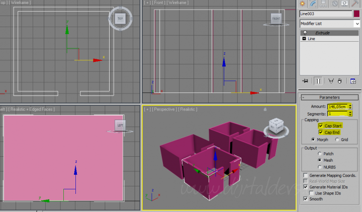
Bir başka örnek
Extrude Menüsü
Amount—Sets the depth of the extrusion.
Segments—Specifies the number of segments that will be created in the extruded object.
Capping group
Cap Start—Ekstrüde edilmiş nesnenin başlangıçı üzerindeki yüzeyi kapatır. Yani yukardaki duvarı Extrude ederken duvarın tabanını kapalı yapar.
Cap End—Ekstrüde edilmiş nesnenin bitişi üzerindeki yüzeyi kapatır. Yani yukardaki duvarı Extrude ederken duvarın en üstünü kapalı yapar.
Morph—Arranges cap faces in a predictable, repeatable pattern, which is necessary for creating Morph targets. Morph capping can generate long, thin faces that don't render or deform as well as grid capping. Use morph capping primarily if you're extruding multiple morph targets.
Grid—Arranges cap faces in a square grid trimmed at the shape boundaries. This method produces a surface of evenly sized faces that can be deformed easily by other modifiers. When you choose the Grid capping option, the grid lines are hidden edges rather than visible edges. This primarily affects any objects assigned a material with the Wire option turned on, or any objects that use the Lattice modifier.
Output group
Patch—Produces an object that you can collapse to a patch object; see the Edit Modifier Stack section in Modifier Stack.
Mesh—Produces an object that you can collapse to a mesh object; see the Edit Modifier Stack section in Modifier Stack.
NURBS—Produces an object that you can collapse to a NURBS surface; see the Edit Modifier Stack section in Modifier Stack.
Generate Mapping Coords—Creates the extruded object with mapping coordinates already applied. When Generate Mapping Coordinates is turned on, additional mapping coordinates are applied to the end caps placing a single 1 x 1 tile on each cap.
Generate Material IDs—Assigns different material IDs to the sides and the caps of the extruded object. Specifically, the sides receive ID 3, and the caps receive IDs 1 and 2.
This check box is turned on as a default when you create an extruded object, but if you load an extruded object from a .max file, the check box is turned off, maintaining the same material ID assignment for that object as it had in R1.x.
Use Shape IDs—Uses the material ID values assigned to segments in the spline you extruded, or curve sub-objects in the NURBS curve you extruded.
Smooth—Extrude yapılan nesneye yumuşatma uygular.
2 boyutlu bir nesneyi 3 boyutlu bir nesneye çevirmek isterseniz. Extrude yöntemini denemelisiniz.
Spline hakkında şuradan ön bilgi edinebilirsiniz.
Öncelikle Line komu ile aşağıdaki gibi bir odanın üstten görünüşünü 2 boyutlu olarak çiziyoruz.

Odayı çizerken, bir çizime nasıl ekleme yapılır ondanda bash edelim.

Aslında 2 farklı çizim yapmış olduk şimdi bu iki farklı çizimi birbirine bağlayalım.
Parçalar üzerinde Convert To: Covert to Editable Spline seçeneğini seçiyoruz.

Attach işlemi yaparak artık iki farklı 2 boyutlu çizimi tek boyuta indirmiş olacağız.

Görüldüğü gibi move yapıldığında tek bir parça gibiler.

Ancak hala işlem bitmedi. Nesnenin tamamını seçerek Weld işlemi uygulamak bu iki nesnenin kaynaşmasını sağlar. Zaten Weld kaynaklama demektir.


Aynı Modifier List içerisindeki Spline bölümünde aşağıda Outline düğmesine basıyoruz ve girdiğimiz Outline değeri nesnemize kabuk yada et kalınlığı veriyor. Böylece duvarları oluşturmuş oluyoruz.

Aynı nesneyi kopyalayıp çoğaltıyoruz.


Nesnelerin hepsini seçip Modifier Listten Extrude seçeneğine tıklıyoruz.

Girdiğimiz Amount değerine göre bir yükseklik tanımlanacak ve odalarımız oluşmuş olacaktır.

Bir başka örnek

Extrude Menüsü
Amount—Sets the depth of the extrusion.
Segments—Specifies the number of segments that will be created in the extruded object.
Capping group
Cap Start—Ekstrüde edilmiş nesnenin başlangıçı üzerindeki yüzeyi kapatır. Yani yukardaki duvarı Extrude ederken duvarın tabanını kapalı yapar.
Cap End—Ekstrüde edilmiş nesnenin bitişi üzerindeki yüzeyi kapatır. Yani yukardaki duvarı Extrude ederken duvarın en üstünü kapalı yapar.
Morph—Arranges cap faces in a predictable, repeatable pattern, which is necessary for creating Morph targets. Morph capping can generate long, thin faces that don't render or deform as well as grid capping. Use morph capping primarily if you're extruding multiple morph targets.
Grid—Arranges cap faces in a square grid trimmed at the shape boundaries. This method produces a surface of evenly sized faces that can be deformed easily by other modifiers. When you choose the Grid capping option, the grid lines are hidden edges rather than visible edges. This primarily affects any objects assigned a material with the Wire option turned on, or any objects that use the Lattice modifier.
Output group
Patch—Produces an object that you can collapse to a patch object; see the Edit Modifier Stack section in Modifier Stack.
Mesh—Produces an object that you can collapse to a mesh object; see the Edit Modifier Stack section in Modifier Stack.
NURBS—Produces an object that you can collapse to a NURBS surface; see the Edit Modifier Stack section in Modifier Stack.
Generate Mapping Coords—Creates the extruded object with mapping coordinates already applied. When Generate Mapping Coordinates is turned on, additional mapping coordinates are applied to the end caps placing a single 1 x 1 tile on each cap.
Generate Material IDs—Assigns different material IDs to the sides and the caps of the extruded object. Specifically, the sides receive ID 3, and the caps receive IDs 1 and 2.
This check box is turned on as a default when you create an extruded object, but if you load an extruded object from a .max file, the check box is turned off, maintaining the same material ID assignment for that object as it had in R1.x.
Use Shape IDs—Uses the material ID values assigned to segments in the spline you extruded, or curve sub-objects in the NURBS curve you extruded.
Smooth—Extrude yapılan nesneye yumuşatma uygular.
 Türkiye (Türkçe)
 Worldwide (English)
 0850 780 4800
 Bilgi Bankası
 Destek Sistemi
 Giriş Yap
 Hesap Oluştur